Optical Lever Sensing Matrices
In this tutorial, we will demonstrate the use of kontrol.OpticalLeverSensingMatrix class, which inherit kontrol.SensingMatrix. kontrol.OpticalLeverSensingMatrix is a general sensing matrix for optical levers with optical lever beams that has tilted incidence plane with respect to the horizontal/vertical plane. Realistically, we won’t be needing this general matrix since optical levers (in KAGRA) are roughly horizontal or vertical. So, we provide reduced version of
kontrol.OpticalLeverSensingMatrix, namely, kontrol.HorizontalOpticalLeverSensingMatrix and kontrol.VerticalOpticalLeverSensingMatrix classes, which are more useful practically.
The derivation of the optical lever sensing matrix is more involved. For details do check out kontrol documentation as well as the documentation of the optical lever sensing matrix. Here, we will briefly introduce the optical lever system in KAGRA as well as some parameters involved, in a step-by-step manner.
Optical lever in KAGRA can be divided into two parts, tilt-sensing and length-sensing. The two uses the same beam and in reality, there is a beamsplitter that divides the beam into two. But, we can assume that they are two separate beams with some common parameters, such as \(\alpha_h\), \(\alpha_v\), \(\delta_x\), \(\delta_y\) and the direction of \(\vec{r}\), as shown in the figures below.
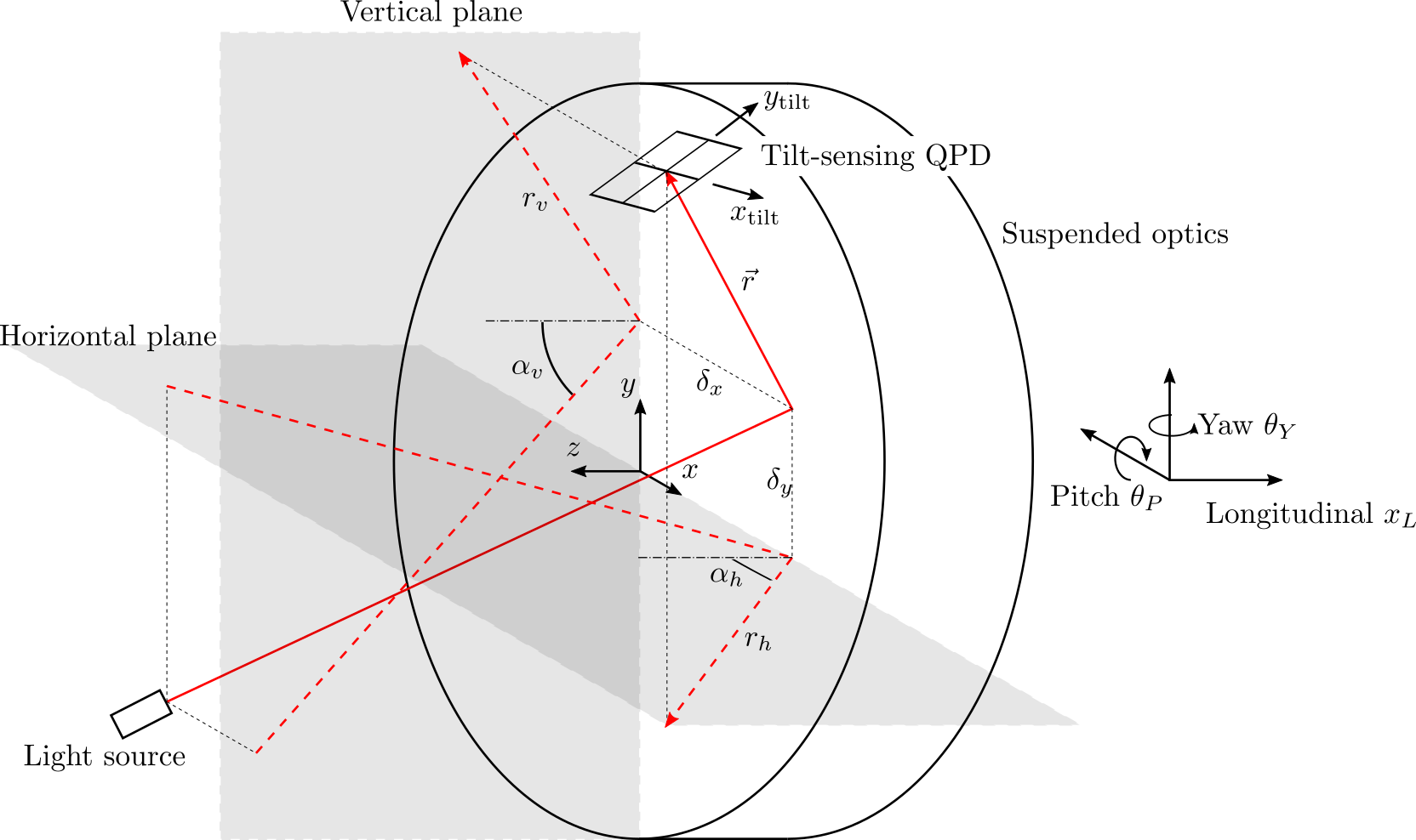

The goal of this sensing matrix is to convert QPD readouts \(x_\mathrm{tilt}\), \(y_\mathrm{tilt}\), \(x_\mathrm{len}\), and \(y_\mathrm{len}\) to the optics’ longitudinal \(x_L\), pitch \(\theta_P\), and yaw \(\theta_Y\) displacements.
The tilt-sensing optical lever can be defined using a single parameter, the lever arm \(\vec{r}\) between optics (in fact, the it’s the beam spot at the optics but we will use optics to refer the beam spot so we don’t have to say it over and over again) and the tilt-sensing QPD. \(\vec{r}\) itself is already enough but it’s not convenient to put it into a matrix. We instead use for parameters \(r_h\), \(r_v\), \(\alpha_h\), and \(\alpha_v\), which are the lever arm and the angle of incidences projected on the horizontal and vertical planes respectively.
Here’s let’s begin by defining some numbers. For demonstration, let’s use parameters from the BS optical lever. here and here. The BS optical lever is a vertical optical lever, so \(r_v=(996+120+185)/1000\), \(\alpha_v = 36.9\pi/180\), \(r_h=r_v\cos{\alpha_v}\), \(\alpha_h=0\). These 4 parameters are sufficient to obtain an initial sensing matrix using
kontrol.OpticalLeverSensingMatrix.
[1]:
import numpy as np

r_v = (976+120+185) / 1000
alpha_v = 36.9*np.pi/180
r_h = r_v*np.cos(alpha_v)
alpha_h = 0

import kontrol

ol_sensing_matrix = kontrol.OpticalLeverSensingMatrix(r_h=r_h, r_v=r_v, alpha_h=alpha_h, alpha_v=alpha_v)
ol_sensing_matrix
[1]:
OpticalLeverSensingMatrix([[0.      , 0.      , 0.      , 0.      ],
                           [0.39032 , 0.      , 0.      , 0.      ],
                           [0.      , 0.488092, 0.      , 0.      ]])
Now we have the initial matrix for converting tilting sensing readout to pitch and yaw. Note that the matrix definition in KAGRA is a map from \(\left[y_\mathrm{tilt}, x_\mathrm{tilt}, y_\mathrm{len}, x_\mathrm{len}\right]^T\) to \(\left[x_L, \theta_P, \theta_Y\right]^T\). It is different from what is writting in the optical lever documentation where the QPD readouts are \(\left[x_\mathrm{tilt}, y_\mathrm{tilt}, x_\mathrm{len}, y_\mathrm{len}\right]^T\). If we want to use the
definition from the document, we can do so by setting the format argument:
[2]:
ol_sensing_matrix = kontrol.OpticalLeverSensingMatrix(r_h, r_v, alpha_h, alpha_v, format="xy")
print("xy\n", ol_sensing_matrix)
ol_sensing_matrix = kontrol.OpticalLeverSensingMatrix(r_h, r_v, alpha_h, alpha_v, format="OL2EUL")
print("OL2EUL\n", ol_sensing_matrix)

## ol_sensing_matrix.format is a property, we can set it on the fly:
ol_sensing_matrix.format = "xy"
print("xy again\n", ol_sensing_matrix)
ol_sensing_matrix.format = "OPLEV2EUL"  # OL2EUL and OPLEV2EUL both works.
print("OPLEV2EUL\n", ol_sensing_matrix)
xy
 [[0.       0.       0.       0.      ]
 [0.       0.39032  0.       0.      ]
 [0.488092 0.       0.       0.      ]]
OL2EUL
 [[0.       0.       0.       0.      ]
 [0.39032  0.       0.       0.      ]
 [0.       0.488092 0.       0.      ]]
xy again
 [[0.       0.       0.       0.      ]
 [0.       0.39032  0.       0.      ]
 [0.488092 0.       0.       0.      ]]
OPLEV2EUL
 [[0.       0.       0.       0.      ]
 [0.39032  0.       0.       0.      ]
 [0.       0.488092 0.       0.      ]]
Note that in here, the matrix values are \(\begin{bmatrix}0&0&0&0\\1.76971116&0&0&0\\0&1.98311972&0&0\end{bmatrix}\) because this is a matrix that converts from QPD counts to longitudinal, pitch, and yaw, whereas kontrol.OpticalLeverSensingMatrix is a matrix that converts from QPD beam spot displacement. To verify, let’s multiply the matrix by the calibration factors from counts to displacements.
[3]:
print(ol_sensing_matrix @ np.diag(np.array([0.004534, 0.004063, 0, 0])*1000))
[[0.         0.         0.         0.        ]
 [1.76971088 0.         0.         0.        ]
 [0.         1.9831178  0.         0.        ]]
This matches almost perfectly with the old matrix.
Now, let’s grab some length-sensing optical lever parameters from here and here, and some misalignment parameters from here.
We have \(r_v = (996+120+185)/1000\), \(r_{\mathrm{lens},v} = (996+120+65+45)/1000\), \(f=300/1000\), \(d_v = \frac{r_{\mathrm{lens},v}f}{(r_{\mathrm{lens},v}-f)}\), \(\phi_\mathrm{tilt}=2.5*\pi/180\), \(\phi_\mathrm{len}=3.5*\pi/180\), \(\delta_x=-0.083\), and \(\delta_y=0.02\).
Note that there’s a typo in here. Beam offsets 0.083 and 0.02 are in meters already, not centimeters, and minus sign because \(+T\) is in the \(-x\) direction, see picture above.
[4]:
ol_sensing_matrix.r_v = (996+120+185)/1000
ol_sensing_matrix.r_h = ol_sensing_matrix.r_v*np.cos(ol_sensing_matrix.alpha_v)
ol_sensing_matrix.r_lens_v = (996+120+65+45)/1000
ol_sensing_matrix.f = 300/1000
ol_sensing_matrix.d_v = ol_sensing_matrix.r_lens_v*ol_sensing_matrix.f/(ol_sensing_matrix.r_lens_v-ol_sensing_matrix.f)
ol_sensing_matrix.phi_tilt = 2.5*np.pi/180
ol_sensing_matrix.phi_len = 3.5*np.pi/180
ol_sensing_matrix.delta_x = -0.083
ol_sensing_matrix.delta_y = 0.02
print(ol_sensing_matrix)
## Alternatively,
# r_v = (996+120+185)/1000
# r_h = r_v*np.cos(alpha_v)
# r_lens_v = (996+120+65+45)/1000
# f = 300/1000
# d_v = r_lens_v*f/(r_lens_v-f)
# phi_tilt = 2.5*np.pi/180
# phi_len = 3.5*np.pi/180
# delta_x = -0.083
# delta_y = 0.02
# ol_sensing_matrix = kontrol.OpticalLeverSensingMatrix(
#     r_h=r_h, r_v=r_v, alpha_h=alpha_h, alpha_v=alpha_v, r_lens_v=r_lens_v, f=f, d_v=d_v,
#     phi_tilt=phi_tilt, phi_len=phi_len, delta_x=delta_x, delta_y=delta_y)
# print(ol_sensing_matrix)
[[-0.00593916  0.0401862  -2.58930873  0.15836891]
 [ 0.38395421 -0.0167638   1.18405437 -0.07241987]
 [ 0.020963    0.48013159  0.          0.        ]]
Again, let’s multiple it by calibration factors to see if it matches that in here. \(\begin{bmatrix} -0.02692811&0.16327656&-6.39818178&0.38816218\\ 1.74084729&-0.06811129&2.92579829&-0.17750109\\ 0.09504626&1.95077516&0&0 \end{bmatrix}\).
[5]:
print(ol_sensing_matrix @ np.diag(np.array([0.004534, 0.004063, 0.002471, 0.002451])*1000))
[[-0.02692813  0.16327652 -6.39818188  0.38816219]
 [ 1.7408484  -0.06811133  2.92579836 -0.1775011 ]
 [ 0.09504623  1.95077463  0.          0.        ]]
Again, it matches almost perfectly.
Now, because this is a vertical optical lever, we can use kontrol.VerticalOpticalLeverSensingMatrix directly. See a self-explanatory demostration below.
[6]:
r = (996+120+185)/1000  # Lever arm from optics to tilt-sensing QPD.
alpha_v = 36.9*np.pi/180  # Angle of incidence on the vertical plane.
r_lens = (996+120+65+45)/1000  # Lever arm from optics to lens.
f = 300/1000  # Focal length of the convex lens.
phi_tilt = 2.5*np.pi/180  # Angle between the tilt-sensing QPD frame and the yaw-pitch frame.
phi_len = 3.5*np.pi/180  # Angle between the length-sensing QPD frame and the yaw-pitch frame.
delta_x = -0.083  # Beam spot offset from the yaw rotational axis.
delta_y = 0.02  # Beam spot offset from the pitch rotational axis.

ol_sensing_matrix = kontrol.VerticalOpticalLeverSensingMatrix(
    r=r, alpha_v=alpha_v, r_lens=r_lens, f=f,
    phi_tilt=phi_tilt, phi_len=phi_len, delta_x=delta_x, delta_y=delta_y)
print(ol_sensing_matrix)  ## Match the matrix above.
[[-0.00593916  0.0401862  -2.58930873  0.15836891]
 [ 0.38395421 -0.0167638   1.18405437 -0.07241987]
 [ 0.020963    0.48013159  0.          0.        ]]